Yale Project Liquid - Water Flow Testing

Project Goal:
Project Liquid is a project within the Yale Undergraduate Aerospace Association that is seeking to build liquid propulsion technology. For this specific project, our goal was to perform a water flow test to test the design of our liquid rocket engine injector and generally validate our test stand fluids, electronics, and structural systems.
My Role:
I was the Technical Lead of the project, meaning that I was responsible for supervising all technical aspects of the design, construction, and testing of our liquid rocket engine. As such, I didn’t have specific parts of the system that I was responsible for, but I was constantly helping others with their projects whenever the timeline began to slip.
Technical Skills Involved:
- Fluid Mechanics
- CAD
- Wiring Electrical Components (Arduino)
- Programming for Data Collection
- Programming for Valve Control
- Basic Construction Techniques
- Aluminum Machining (lathe, CNC mill, etc)
Other Skills:
- Project Leadership
- Test Procedure Creation
- Test Logistics Management
- Technical Communication with Various Stakeholders

Technical Overview:
This test was meant to be a way to validate all parts of our system and general test operations. Below, I provide a summary of each of these systems:
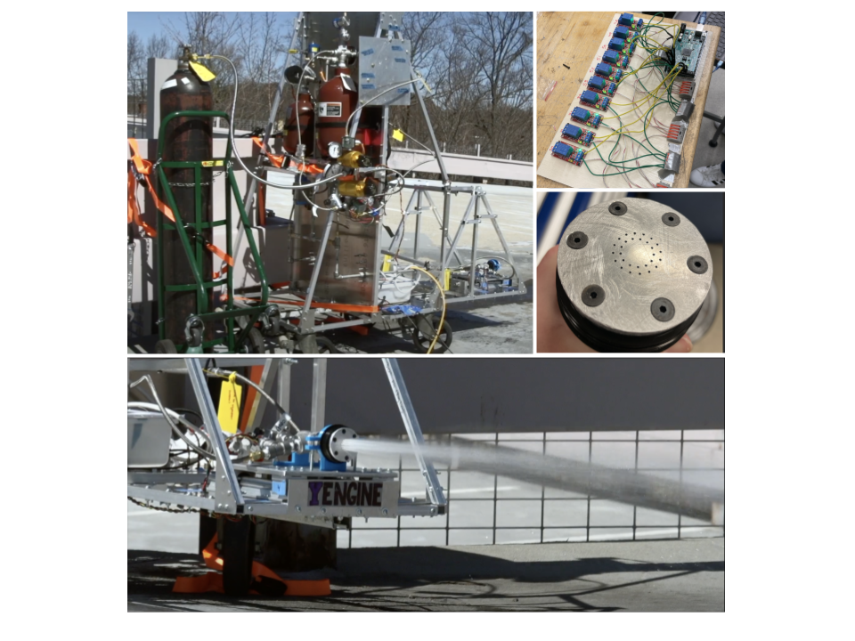
- Thrust Chamber:The primary objective of this test was to observe the atomization of the output of the injector plate. I actually helped design the initial injector plate, which uses a coaxial sheer design achieved with hypodermic needles passing through a lower manifold. These manifolds were achieved with a stacked design that were separated by O-rings. The engine, entitled Yengine 1.0 (Yale + Engine) was designed to achieve 200 lbf of thrust with nitrous oxide and IPA. The chamber and forward wall were both taken from a refillable solid cylinder with the forward wall modified to accept the liquid injector.
- Fluid Supply System:Our system used two tanks to store propellants (although both were used for water in this test). For this test, the two tanks were pressurized with a nitrogen gas tank and a regulator up to 300 psi to simulate the 300 psi pressure drop that was intended across the injector once the system was pressurized with propellants up to ~750 psi (as determined by the vapor pressure of nitrous oxide). A network of pipes and solenoid valves were used to control the flow of water and nitrogen through the system, giving us the ability to pressurize and vent the water we had in the system. Two pneumatic ball valves were used as the run-valves (or pre-valves) of our system because of their higher cv values.
- Electronics & Control:The electronics system used an Arduino microcontroller to connect to the control laptop. This Arduino and the digital pressure transducers it used used a 5V architecture while the valves ran on a 120VAC architecture. These valve actuations were controlled by the Arduino using relays. A Graphical User Interface (GUI) was used by the team to input commands and read the values of the pressure transducers.
- Test Stand:Our system was supported by an aluminum test stand which held all of the components and used wheels to provide mobility. Due to lack of access to welding, fasteners were used to hold together the entire assembly. The injector itself was mounted on a sliding plate that moved against a load cell so that we could collect thrust values from the chamber if actually static fired.
Results:
In general, this test was a massive success for our club. Although there were certainly some technical challenges and takeaways that we have incorporated into designs since (see list below), this demonstrated a significant step in the journey of our club. We learned a lot technically and operationally, and the day was generally a lot of fun for members. Just getting to this point required a massive amount of time and investment from me personally, and despite the areas of improvement in the design, I was still proud of what our late nights were able to produce. Alongside a video created by some people on the team about the test, I included a list of technical takeaways that have been used to create Project Liquid’s following project - an augmented spark igniter (ASI).
Technical Takeaways:
- A 24 V architecture would be easier and require less approval from administration than a 120 VAC architecture like the one used here.
- Using tubing and compression fittings would reduce our dependence on certain orientations as we found was problematic with NPT piping.
- A problem within our injector damaged the seal between the manifolds. This could have been very problematic for an actual propellant-based test and has resulted in a completely different injector design for current Project Liquid engines.
- Slotted extrusions would make assembling and modifying the test stand a lot easier than with the square extrusions we used previously.